Integrated Process Design of a Rice Hull Carbonizer System

Cathy Wang • June 23, 2025

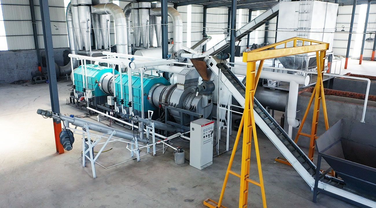
The rice hull carbonizer represents a practical solution to transform agro-waste into high-value biochar through thermochemical conversion. Known for its high ash and silica content, rice hull requires controlled carbonization to ensure effective transformation and yield stability. The workflow of a carbonization system engineered for rice hull is built upon a modular yet continuous thermal processing framework.

Feedstock Preparation and Preconditioning

The process begins with feedstock conditioning. Rice hull, although dry in most post-milling environments, often exhibits non-uniform particle size and moisture content. A screening system removes oversized impurities such as small stones or grain remnants. If moisture exceeds 15%, a belt dryer or rotary drying drum is engaged to lower humidity to operational thresholds.

Stable moisture content ensures thermal efficiency and avoids incomplete pyrolysis or excessive smoke generation. Fine control in this phase enhances both throughput and downstream carbon quality of rice hull carbonizer.

Automated Feeding Mechanism

Dried rice hull is then conveyed via a screw or sealed belt system into a buffer silo. From this point, it is gradually introduced into the carbonization furnace using a frequency-controlled auger feeder. The feeding system must maintain an oxygen-limited environment to prevent premature combustion, ensuring the hull undergoes thermal decomposition rather than burning.

This sealed feed-in system plays a crucial role in maintaining process continuity and optimizing fuel-to-char conversion rates.

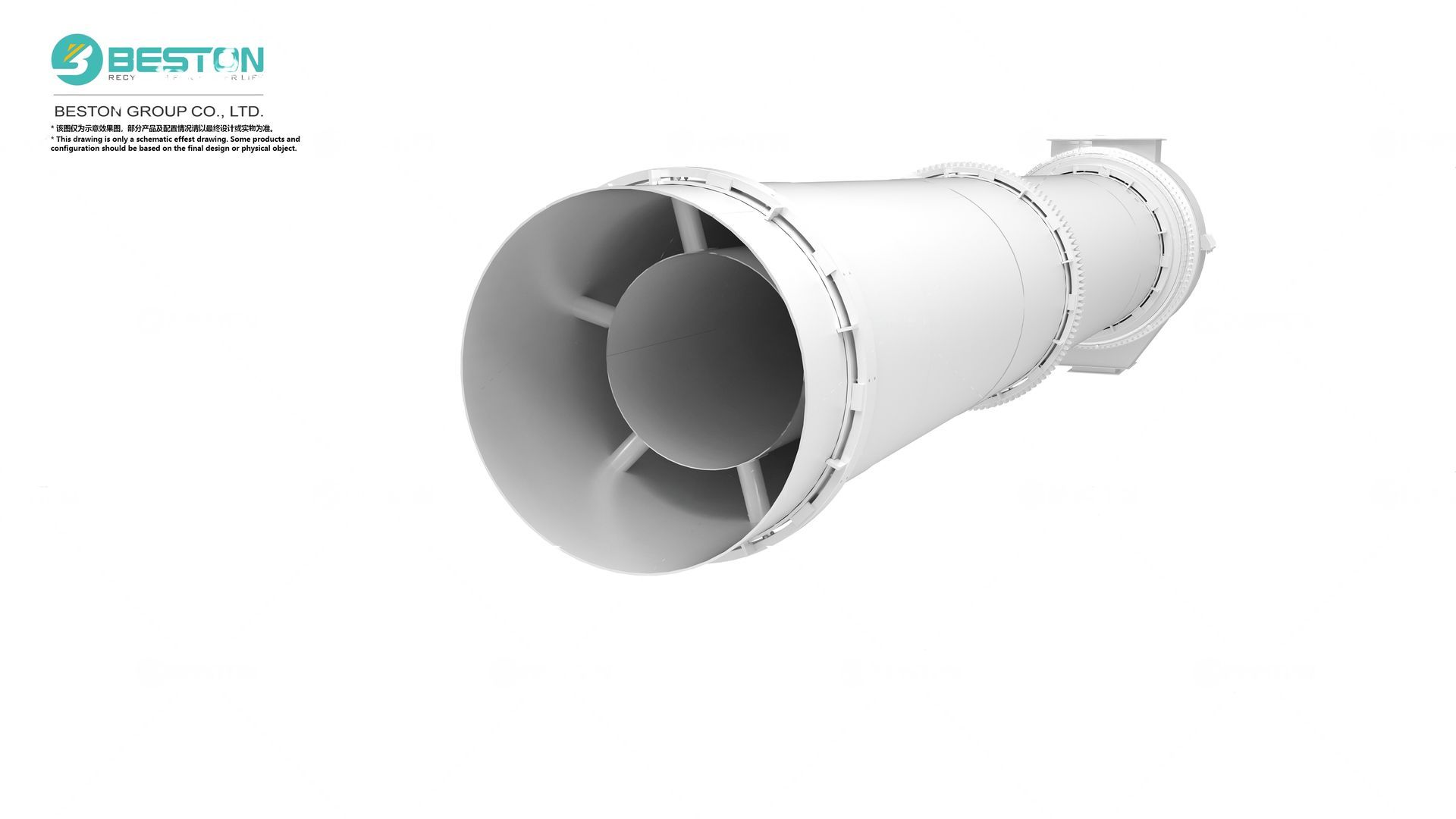
Primary Carbonization Chamber

The heart of the system is the carbonizer reactor—a horizontal cylindrical vessel, typically constructed from refractory-lined steel. Inside the chamber, rice hull is exposed to indirect heating in the temperature range of 350–600°C. The heat source can be biomass combustion, syngas recycling, or natural gas, depending on facility design.

Thermal decomposition occurs in an oxygen-deprived setting, breaking down volatile components and leaving behind fixed carbon. Volatile matter exits as a combustible gas mixture, while the remaining solid residue converts into porous biochar with high surface area.

Residence time and temperature gradients are adjusted via control panels and PLC systems, allowing operators to finetune the char structure for specific end-uses such as soil amendment or filtration.

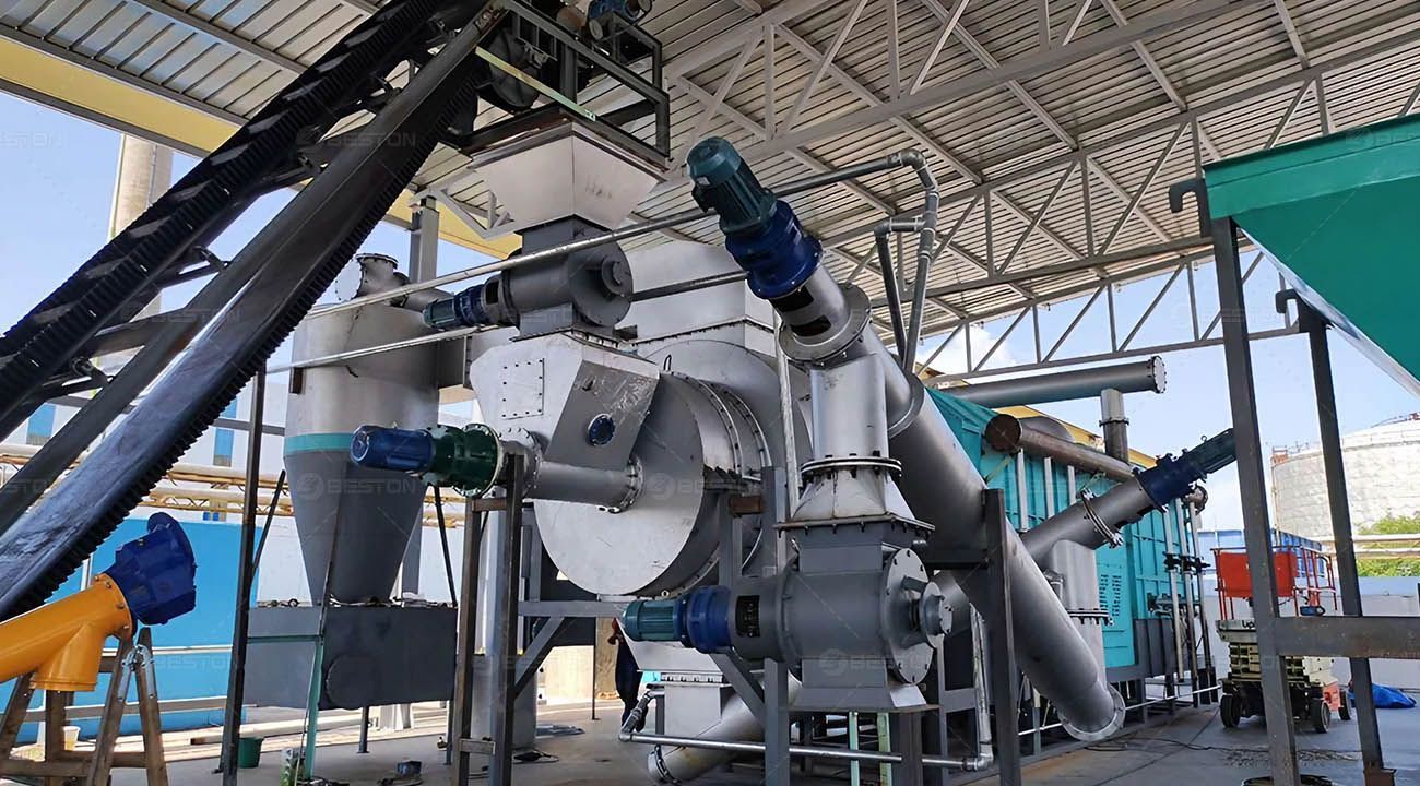
Gas Recovery and Cleaning

The vaporized byproducts from the carbonization chamber are directed through a gas separator where char dust is removed. The remaining condensable gases, primarily tar, moisture, and light hydrocarbons, enter a condensation system. Water-cooled exchangers convert these vapors into liquid tar and aqueous byproducts.

The non-condensable gas—syngas—is stored in a buffer tank and partially recycled back into the burner for heat supply. This internal energy loop minimizes external fuel requirements and boosts system energy efficiency.

Emission control units, such as spray towers or activated carbon filters, treat residual off-gases to meet environmental discharge standards.

Char Discharge and Cooling

After the carbonization phase is completed, the hot biochar exits the reactor through a sealed discharge screw and is transferred to a water-cooling or air-cooling section. Proper cooling ensures safe handling and storage without the risk of spontaneous combustion.

The final product is collected in silos or packed for immediate sale, depending on processing flow. Optional pelletizing or grinding modules can be added to match market-specific specifications.

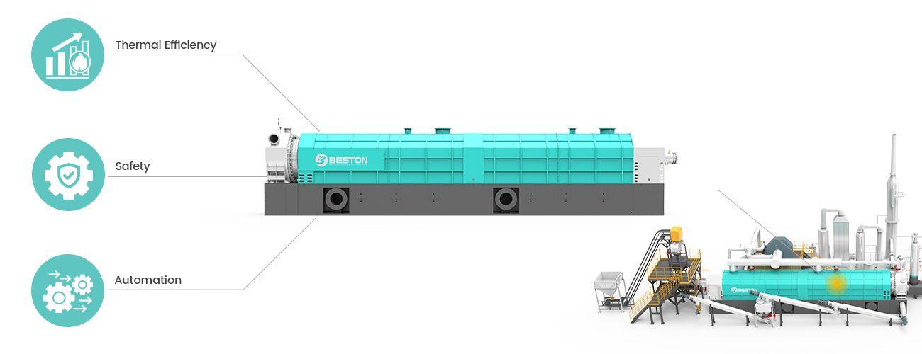
Control and Safety Systems

Advanced rice hull carbonizer systems integrate real-time control via programmable logic controllers. Thermocouples, oxygen sensors, and automated dampers are employed to regulate air flow, prevent backdraft, and adjust heating profiles dynamically. Emergency stop systems, pressure relief valves, and interlocked conveyors form part of the safety infrastructure.

Workflow Summary

  1. Pre-drying and screening – Ensures optimal moisture and purity
  2. Sealed feeding – Maintains inert conditions
  3. Carbonization reactor – Controlled thermal decomposition
  4. Gas condensation and recycling – Energy efficiency and tar separation
  5. Char discharge and cooling – Product stabilization
  6. PLC monitoring and safety management – Operational stability

The rice hull carbonizer operates as a continuous, low-emission system capable of converting voluminous agro-waste into industrial-grade biochar, while minimizing fuel consumption and labor intensity through integrated automation. Its workflow is a culmination of thermal engineering, process control, and environmental safety, providing a scalable path to biomass valorization.

By Cathy Wang December 10, 2025
Digital measurement, reporting, and verification (dMRV) has become a central scaffold for ensuring credibility in carbon dioxide removal (CDR) pathways. Biochar projects, particularly those operating through a pyrolysis plant, rely on rigorous instrumentation and well-structured data methodologies to substantiate their climate claims. dMRV provides an auditable, transparent mechanism for quantifying carbon flows, tracking operational parameters, and validating long-term sequestration performance. The Role of Data Fidelity in Biochar Carbon Accounting Accurate carbon accounting begins with data fidelity. Biochar generation is governed by thermochemical transformation, and even slight variations in feedstock moisture, reactor temperature, or residence time can alter carbon yield. A sophisticated dMRV architecture mitigates these variances by capturing high-granularity data directly from the biochar machine control system. Short data pulses—temperature peaks, pressure fluctuations, or syngas volume anomalies—are complemented by long-interval metrics, such as cumulative biochar output and ash ratio. Together, they create a defensible audit trail. dMRV platforms elevate these raw measurements into structured datasets using metadata such as timestamps, sensor calibration records, and process batch identifiers. This allows project developers, validation bodies, and registries to corroborate carbon retention claims with mathematical precision. Process-Level Tracking Within Modern Pyrolysis Infrastructure A biochar CDR project hinges on understanding every stage of thermochemical conversion. Integration between the digital system and the biochar pyrolysis machine fosters predictive analytics and near-real-time oversight. Key process parameters typically captured include: Inlet feedstock composition: lignocellulosic ratios, particle density, and contamination levels. Thermal trajectory: reactor ramp-up curves, sustained high-heat phases, and cooldown profiles. Syngas composition: hydrogen concentration, methane traces, and condensable tars. Biochar output characteristics: carbon fraction, aromaticity (H/C_org ratio), and pH value. These datapoints feed into carbon permanence calculations. Because biochar stability depends on its aromatic carbon fraction, having precise chemical signatures ensures durability forecasts—often modeled over centuries—are evidence-based rather than speculative. Digital Verification and Chain-of-Custody Beyond quantifying carbon, a biochar CDR project must prove that generated material is transported, applied, or stored according to protocol. dMRV extends into a chain-of-custody system that may include tamper-evident QR codes, GPS-anchored delivery logs, or photo-verified deployment events. Such tracking prevents double-counting and strengthens the integrity of carbon credit issuance. When biochar is dispersed onto soils, integrated geospatial layers reveal application zones, tonnage distribution, and compliance with agronomic thresholds. Lifecycle Modeling and Emissions Reconciliation Lifecycle assessment (LCA) is indispensable for discerning net carbon removal. A robust dMRV system includes automated reconciliation workflows that incorporate upstream and downstream emissions, such as: Feedstock harvesting and preprocessing. Transportation to the pyrolysis plant. Energy consumption during thermochemical conversion. Post-processing, packaging, and movement of biochar. Digital reconciliation ensures that every emission source is accounted for before final net-removal figures are generated. This prevents inflated claims and aligns with emerging international standards for CDR disclosures. Integrating Remote Sensing and Edge Devices Many contemporary dMRV solutions employ remote sensing for environmental verification. Multispectral imagery, drone-assisted inspections, and satellite analytics provide corroborating evidence of land-use patterns, biomass availability, or soil application extents. At the facility level, edge devices mounted on conveyors, reactors, and storage silos reduce manual input error. They preload verification data directly into encrypted ledgers, enabling continuous monitoring without operational downtime. Automation, Transparency, and Audit Readiness A biochar CDR project must maintain perpetual audit readiness. Automated data pipelines significantly reduce the risk of human-induced discrepancies. Immutable logs—often maintained via distributed ledger technology—ensure traceability across every process node. Transparency is reinforced through standardized reporting templates that present auditors with concise, well-structured evidence: parameter trends, calibration cycles, non-conformance alerts, and remediation actions. This systematic approach enhances market trust and accelerates credit issuance cycles. Scalability Considerations for Global Deployment Scaling biochar-based CDR demands interoperability. dMRV systems should support modular expansion, allowing additional pyrolysis plant units, feedstock streams, or regional hubs to be integrated without data fragmentation. Open APIs, machine-readable reporting formats, and harmonized taxonomies ensure that multiple facilities can align under a unified verification architecture. This is particularly critical when operating across jurisdictions with divergent environmental regulations or registry requirements. Future Trajectories in Biochar dMRV Technological evolution continues to refine the rigor of biochar CDR monitoring. Advanced spectroscopic tools may soon enable continuous carbon-stability profiling during production. Machine-learning models could predict reactor anomalies or optimize carbon yield based on historical trends. As regulatory frameworks mature, dMRV systems will likely incorporate standardized carbon integrity metrics, automated third-party verification triggers, and cross-registry synchronization for global transparency. Advancing High-Integrity Removal Through Rigorous Digital Infrastructure A biochar CDR project anchored in a precise, tamper-resistant, and scalable dMRV system is positioned to deliver trustworthy carbon removal outcomes. Data-centric governance enhances credibility, optimizes reactor efficiency, and substantiates permanence claims. The convergence of thermochemical engineering and digital verification practices forms the backbone of reliable biochar deployment, enabling stakeholders to contribute meaningfully to long-term atmospheric carbon reduction.
By Cathy Wang November 24, 2025
Africa is witnessing a rapid surge in urbanization, motorization, and industrial expansion, which collectively generate unprecedented volumes of end-of-life tires. With limited landfill space and growing pressure to curb uncontrolled dumping and open-air burning, the region has begun turning toward technologically viable resource-recovery solutions. Among these, a modern pyrolysis plant has emerged as a strategic asset. It converts discarded tires into pyrolysis oil, carbon black, steel wire, and combustible gas—products with strong commercial traction in both local and export markets. The scale of tire accumulation, combined with new environmental regulations, positions tire pyrolysis plant as a timely and profitable sector across the continent. Robust Availability of Feedstock End-of-life tires are abundant in Africa due to aging vehicle fleets, limited recycling infrastructure, and low entry barriers for imported second-hand tires. In nations such as Nigeria, Kenya, South Africa, Ghana, and Tanzania, millions of tires are discarded each year. This stable and inexpensive input stream offers a significant economic advantage. Key Advantages Minimal competition for feedstock supply Lower collection costs compared with developed markets Presence of informal waste aggregators who support continuous sourcing Such conditions create long-term predictability for project developers seeking secure supply chains.
By Cathy Wang November 18, 2025
The management of oil-contaminated soil has become a critical environmental issue, particularly in areas affected by industrial operations, spills, and accidental discharges. Traditional soil remediation techniques often fall short in terms of efficiency, environmental impact, and cost-effectiveness. In contrast, thermal desorption presents a viable solution for addressing these challenges, offering a range of benefits in the restoration of contaminated sites. By utilizing a thermal desorption unit, the removal of oil contaminants from soil can be achieved effectively, ensuring a cleaner, safer environment and compliance with environmental regulations. Efficient Removal of Oil Contaminants One of the primary advantages of using a thermal desorption unit in the remediation of oil-contaminated soil is its efficiency in removing organic pollutants, particularly oils and hydrocarbons. The thermal desorption process involves the application of heat to soil, causing volatile contaminants, including oils, to vaporize. These contaminants are then captured, condensed, and separated from the soil, effectively purging the material of harmful substances. This method is particularly effective for dealing with soils contaminated by petroleum-based products, such as crude oil, diesel, and lubricating oils. It is ideal for large-scale cleanup operations where time is a crucial factor, as thermal desorption can process significant volumes of contaminated soil in a relatively short period. The precision and speed of this process ensure that oil residues are removed from deep within the soil matrix, something that traditional methods, such as bioremediation, may struggle to achieve.